31 January 2024

First prints after a while

First printing project after a while

With most of the software and firmware ready, I was up to do some printing. I recalled the hardship of leveling my bed, and thought that a good staring point would be nobs to adjust the heated bed level.

I am using M3 bolts. Following Wikipedia, I figured out the step of standard screw, which is 0.35mm for every revolution. By making a 7-teeth rosette, with every "leaf" turn, I would change the bed's height by 0.05mm. Sounds awesome, lets design. You can get the CAD from my public Onshape project here.

The slicer: time for Ultimaker

During my stay in Germany I had the pleasure of meeting people who were also hooked on 3d printing. I recalled Johannes speaking highly about Ultimakers software as a "printing command center". At that time (like 7 years ago) Ultimaker was actually supporting RepRaps and print-over-USB. Sadly for me - not anymore. Greater reliability of SD card control or wireless control with remote hubs, Ultimaker removed the option to control the printer over the cable. Still, one could add a custom printer that was controlled by Repetier firmware! I decided to relieve Ultimaker from the control duty, relying on good old Pronterface, and use Ultimaker as plater and slicer.

In the beginning I was a bit overwhelmed with the amount of options available. Things have definitely moved on. Yet the overall setup was rather self-explanatory and easy to understand. I definitely appreciated the tooltips over every setting. 

With slicing done and g-code loaded up to Pronterface, it was time to print!

The prints

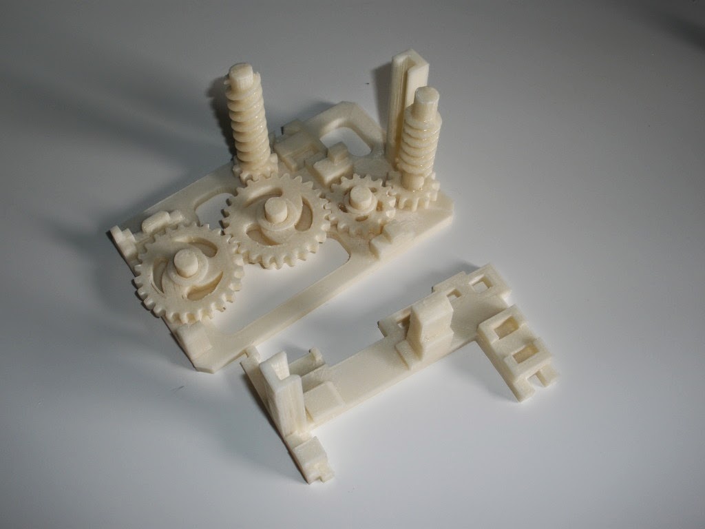
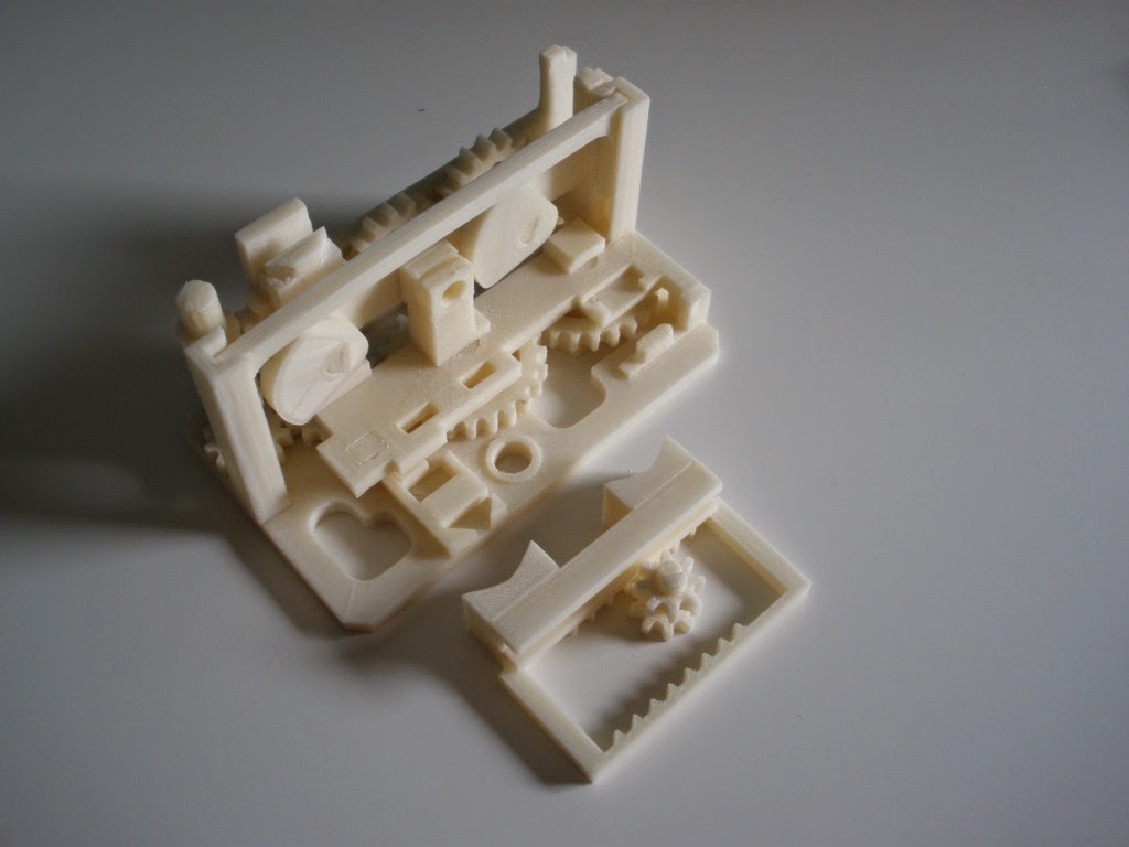
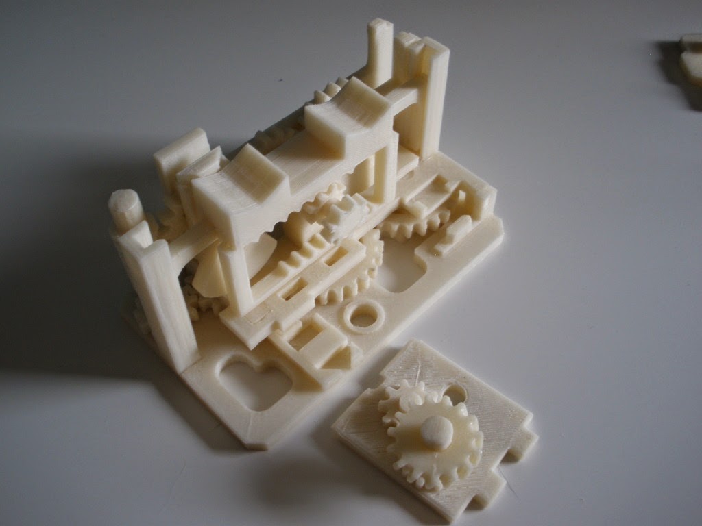
The first prints were quite challenging due to reasons not clear to me at that time. Although the first layer seemed to nicely fill and the following layers appearing, something was off.

The image is a small compilation of the attempts made. There were problems with delamination, constant nozzle blockages, driving bolt "eating" filament and clogging teeth... Interestingly enough supposed that I "survived" the first solid layers, paused the printer to clear the hobbed bolt, then for the infill layers things would go rather smoothly. Only after getting to top full layers, the issues would appear again, often making the printer not extrude for the final layer (or two). Fortunately, since these were work-parts I did not care if the layer was missing or if parts ended up a bit skewed. After an evening or two of attempts, I was holding a set of 4 bed adjusters. I mounted them on the printer and have been using them with great success since then! Bed leveling was never easier!

Oh and yes, I am aware that these could/should be mounted on the bottom, not to interfere with the extruder. I am actually planning to re-mount them, but for now they are OK and it is easier for me to manipulate them that way. Also the Y-axis movement prevents me from using last 2cm of the bed, and the glass bed clippers (in the background) also remove extra 1cm from each side. I might work on this at some time but for now I do not need the whole bed anyway.

In the next post I will show the X- and Y- belt tensioning elements plus I will reveal what was wrong with the extrusion settings.


02 January 2024

Repetier firmware on RepRap with Gen 7 electronics

Getting new firmware on an old printer is not that easy, especially when one assumes that new tools are backward compatible. With multiple possible points of failure it becomes a game of cat and mouse to figure out which one works with another.

The right Arduino

My Gen 7 electronics uses an Arduino ATmega 1284P PU 1211 with a 20.000 MHz clock. Thought it seems tempting to use newer Arduino IDE's for updates, things get interesting when we want to use old Gen 7 board support files. Newer Arduino IDE's do not have a straightforward way of manually adding custom boards. Or perhaps they do, but that would require me to write the whole custom board support. At some point I was actually tempted to do that, but first decided to test older IDE's. That was a good call.

Arduino 1.0.3 IDE worked.  You can get it from official Arduino's old releases repo. While it does not have many awesome new features, it shines in one bit way: you can add custom boards just by dropping the configs in ./hardware/ folder, which I did.

The right Gen 7 board support

The right Gen 7 support is the latest one, that is Gen7 Arduino IDE Support 2.1. which is still hosted on RepRap's wiki. 

The right Repetier firmware

Of course the newest ones did not work... But by trial and error I figured out that the working version was Repetier 0.91, which you can configure and then download from https://www.repetier.com/firmware/v091/

There was a small caveat - the old C++ compilers that come with Arduino 1.0.3 IDE do not recognize the rounding function lroundf() which converts floats (fractional numbers) to long integers (non-fractional numbers). I could mess with getting the right C++ compiler, but it was easier for me to edit the code and just map the float type to long. Yes, I loose some precision since this just drops all the fraction and does not round up, but It was faster that fighting with the compiler and the possible precision loss seems minimal.

The final product

After a couple of days (if not weeks) I had my "new" firmware uploaded and working on the printer. The pronterface was able to communicate with it, the Cura slices with Repetier's flavor were properly read, so we were ready to print.
For reference (and safekeeping), I hosted on Github the config files, gen 7 and Repetier stuff.

18 December 2023

Get it clean, get it moving!

Lets just start it!

One of the first things on my list when restarting with the printer was to try kicking it off on my current PC. Despite being given multiple awesome opportunities by Microsoft to upgrade my system, I am still mostly using Windows 10.

Getting Printrun and Pronterface running was surprisingly easy. Yes, the official sites are a bit outdated, but the community is not completely dispersed. Amazing kliment still runs a github with latest repo: https://github.com/kliment/Printrun/releases I got Printrun version 2.0.1.
Of course I needed to have Python 3.6 on the system. I can not recall now whether I had to compile the source (I believe not), but even if I did, it was very straightforward.

With Pronterface added as a shortcut to my start menu, I was ready to start! A couple of days prior I cleaned the whole printer with a compressor. When powered it did not burn. I started Pronterface, connected, gave a command and the printer moved!
The old Teacup firmware was still kicking. But I wanted something newer.

Better - worst enemy of good

I recalled Johannes mentioning Ultimaker's Cura as a great slicer and printer control. Well, it did not run Teacup, so I decided to go with Marlin firmware... That was a mistake... Not that Marlin is bad, but... Cura did not support print-over-USB anymore... Plus it did not like my Gen 7 1.4.1 electronics... Plus Marlin was not super easy to upload... But I already tried and erased Teacup from printer's Arduino... That was a bad move...

Dealing with unintended consequences

Not discouraged, I got a new plan. First: get new firmware. I selected Repetier, since it was nicely supported by Cura, which I intended to use as a new slicer. Then try to force old versions of Cura to guide my printer over USB, then move all that to some light Ubuntu distro on a laptop and run the ABS melting in my basement instead of office. This was a start of an interesting and bumpy journey...


11 December 2023

Resurrecting the printer - back after 9 years

It has been a while. Couple of years passed. Couple of changes happened. The last post describing the walking-beam project was written while I was still living in Italy. Since then I moved to Germany, stayed there for almost five years and moved back to Poland. I switched between a couple of jobs, extended my family and basically reduced hobby related activities. Through all these years I kept dragging the printer along. While in today's standard it is not even close to what is available on the market and I could get a new machine for a couple of euro. It was always a hobby project - a thing self made. A bit rough, a bit crude, but mine. And it still works!

As I am writing this, I realize how much I have not had written. There were several small projects that I did back in Germany. Be this the homage to my insufficient writing skills or even little reservations to share my "life" online. Still I recognized how useful this blog was when trying to resurrect the machine and how lacking it was in terms of proper data organization and presentation.

At this moment (again) I moved forward with the "Resurrection project" far beyond the scope that can be described in one post. I see the need to preserve this knowledge. I hope to do that on this blog and hope the experience I have gotten over the years will help me do a better job in organizing the information in a useful manner.

In the coming posts I intend to describe the process of how I managed to start-up a machine that was lying dormant for almost a decade. I will describe the required hardware adjustments and struggles with using ancient software. While I still face multiple issues when printing, each is a new experience and a shard of knowledge that helps me improve my understanding of 3d printing.

Upcoming: Teacup firmware replacement with Repetier, running Printrun on Win10, running Printrun on Lubuntu (Light Ubuntu), remote X sessions with Ubuntu, fixing and replacement of old printer parts, first prints: printing bed adjusters, X and Y belt tension adjusters and possibly some nostalgia posts.

See you later!

09 July 2014

The Walking Beam Project

Ladies and Gentlemen,
It is my honor to present the crown achievement of Pawel’s 3d printing craftsmanship so far! The Walking Beam project! Brace yourselves- a long post is coming!
It would be good at the beginning to explain what is a walking beam and how did I get the idea to make one? I am working in sales of steel industry at the moment. We are dealing with lifting of steel coils that weight tens of tons. A coil can be sometimes 2 meters in diameter and weight for example 35 t. In order to speed up feeding of processing lines, the coils are put on “saddles” and then transported by special cars or by walking beams. A picture tells a thousand words, so here is a scheme of walking beam in action.
The coil rests on a saddle (1). The beam is lifted with the coil resting on it (2). Then it moves to next position and is lowered (3). The coil now rests on next saddle and the beam moves back to the starting position (4). It is easy to imagine that the beam can be longer than 3 saddles, and that it can transport more coils at the same time- smart and very effective.
I decided to make a model of such a machine that would transport wine corks.
The big industrial walking beams are driven by powerful hydraulic cylinders. My goal was to make everything mechanic (gears). I also wanted to have only one “power source”- a single rotating handle that would go in one direction and allow for all the cycle to take place. Furthermore it would be fun to rotate the handle several times before the cycle was done. The target were 3 handle rotations to lift/lower the beam and 5 rotations to move it left/right.
The question was: how do we make the machine first to lift the beam (keeping it still in horizontal direction), then move it only left, then down and then right? I needed two systems: lifting and transverse. Each needed to have its “action phase” (move or lift) and a “pause phase” (when the second system would be working). They should also be able to automatically switch between each other. And of course all had to be driven by one handle going rotating in one direction :)
First let’s talk about the lifting system. The heart of the mechanism I used looks the following:

I divided 360 deg into 3/16, 5/16, 3/16 and 5/16, that is 67.5 deg, 112.5 deg , 67.5 deg and 112.5 deg (three rotations for lifting and five for transverse, remember?). The 5/16’s are parts of two circles representing “pauses”. Their radius difference is equal to desired lifting distance. The 3/16’s are the lifter’s “action phases”. The beam is resting on the top of the lifter, which is rotating with constant speed. The animation below demonstrates how it works.

Now it is time for transverse movement. How to make it go left, pause, then right and pause when the drive is rotating in the same way? At first I thought about some particular half-gears with reducers and different number of intermediate gears. This seemed a bit complicated though- it will do nicely as another project. For my walking beam I used a simpler solution. I fixed the transverse drive gear (TDG) in one spot and made it rotate with constant speed in one direction. Then a frame was put “around it” with teeth on the top and bottom. Depending on whether the TDG is touching top or bottom teeth, the frame would move left or right. The lifting system was used to change which teeth are touched. I got the “action phase”, “pause”, “action” and “pause”. In addition, to prevent unwanted movement, final teeth in the frame were removed. The schematic animation below shows the idea in action:

This system has one big flaw- it can only transport the corks in one direction. At the same time it is simpler to implement and more robust to inaccurate synchronization.
Having the idea fixed I started designing the machine. I calculated gear reductions, movement distances, general overlay- well, some theoretical stuff. Then it was FreeCAD time. Finally I had an excuse to learn a bit Python. It was not very tempting to make every gear or spiral “by hand”, and having a nice procedure that could do it for me made my life much easier. Especially that there were lots of different gears to be done.
I was advised by the organ between my ears to first allocate the moving elements in space and then think how to make the supports and frames. The machine was supposed to be compact and should allow for easy dismounting and access to the parts. And of course each element was to be designed in a way that would allow printing it. It took quite a few evenings, few weekends and finally I got the design ready:

Doesn't it look awesome already?
One could ask: “why didn't you start printing when you had some parts of the design ready”? Well I did. At least few gears that I knew that were in their “final” form were printed during FreeCAD period. The rest was being modified a lot on the way. Fixing any shape by printing it puts a big constraint on other part’s shape. Being perfectly honest- I made one or two design mistakes on the way but in the end the errors were insignificant. I was able to repair them with few moves of a file and a tiny bit of glue.
In general all the parts were printed in their desired final shape and required only surface cleaning from the printing residual trash. Most important elements’ surfaces were additionally treated with acetone to get a nice smooth finish. Also due to 3d printing limits five parts were intended to be made of several elements glued together.
OK enough talking! Here are all the elements of the “Walking Beam”! Next pictures show the assembly of the whole machine. Isn't it even more awesome?

I am particularly proud of the spirals. If you take a closer look, they have different slopes and one is a single helix while the other is a double helix. For the double helix system I also had to make the gear with inclined teeth so it could fit within the gap. Here are some close-up pictures.

Finally I present to you the movie with the Walking Beam in action!

Thanks for sticking this long. I do hope you (or at least your inner-geek) enjoyed the content. I had great fun making this project and am looking forward to doing some more. Your “views”, “likes” and “shares” are an awesome recognition to all this effort and for sure will boost my engines to spend more time on 3d printing. Thank you!

01 July 2014

Tablet drive- GCodePrinter

When I was looking through the old posts for the total price of the printer I noticed that there was a plat to buy an old PC to run the control software on.
It is no longer the case. Some time ago I got a Lenovo tablet as a present. In the Google Play Store I noticed an awesome application called GCodePrinter. It costs like 4 euro and changes your toy-tablet into a mighty tool for steering devices of the future! OK, I I got a bit too excited ;)
If your tablet has this magic cable that allows USB to be connected to it (for memory sticks etc), you can try to put the printer under its control. Here is a picture of my printer being driven by a tablet. It looks super geeky great and works too!

Spoiler: the printed part is an element of the big awesome project.

As I wrote, it looks nice and all. Unfortunately it might get into some trouble. I made some nice prints, but one time it happened that the tablet went to hibernation (or something) and second time there was some communication error. This of course resulted in the stop of the print, and the part got wasted (I still have to find out a way to safely restart broken prints). For that reason, although it looks cool, I prefer to print bigger parts under PC control. It simply seems more reliable.

30 June 2014

Y-axis upgrade

I mentioned in the previous post that for the last months I was working on a bigger project with the 3d printer. Just at its beginning I noticed that there was something wrong when circular objects were printed. They were a bit oval, definitely not nice and circular. I figured out that this is because of loose tension on the Y-axis belt. I could theoretically adjust the tension on the end points where it is attached to the moving bed. Unfortunately way my printer is built makes it a bit hard to do (you would have to dismount a big piece of the bed which is tricky to put back together).

The printer worked but the results, especially the precise ones with complex and circular borders did not look very well.

I decided to add a new part that would divert the belt a bit thus putting required tension on it.

After a short session with FreeCAD, even shorter slicing in new version of Slic3r and around half an hour of printing I had the necessary part. After adding the metal screws with some nuts and using spare bearing and washers the part was installed onto the printer.


The results after the upgrade were very satisfying. The circular objects looked circular :) After this moment I was convinced that was ready to work on parts that require decent level of precision.

A small digression- during the printing a major damage happened twice to the Y-axis pulley gear (you can see it in the picture above). It broke at its bottom. Of course I had to print the part and replace it. As you can image since the printer was broken it was not an easy task. Fortunately the glue held long enough to make the new print. It seemed that there will be no trouble but the part broke again. It seems the tension on it is too big (the engine's shaft is not going all the way through the pulley). The second time I made the part full in plastic- no saving for inner layers. I also treated the surface with acetone vapor to make it even stronger. Till now all is good. Of course I made an additional spare pulley (just in case) :)