Ladies and Gentlemen,
It is my honor to present the crown
achievement of Pawel’s 3d printing craftsmanship so far! The
Walking Beam project! Brace yourselves- a long post is coming!

It would be good at the beginning to
explain what is a walking beam and how did I get the idea to make
one? I am working in sales of steel industry at the moment. We are
dealing with lifting of steel coils that weight tens of tons. A coil
can be sometimes 2 meters in diameter and weight for example 35 t. In
order to speed up feeding of processing lines, the coils are put on
“saddles” and then transported by special cars or by walking
beams. A picture tells a thousand words, so here is a scheme of
walking beam in action.
The coil rests on a saddle (1). The
beam is lifted with the coil resting on it (2). Then it moves to next
position and is lowered (3). The coil now rests on next saddle and
the beam moves back to the starting position (4). It is easy to
imagine that the beam can be longer than 3 saddles, and that it can
transport more coils at the same time- smart and very effective.
I decided to make a model of such a
machine that would transport wine corks.
The big industrial walking beams are
driven by powerful hydraulic cylinders. My goal was to make
everything mechanic (gears). I also wanted to have only one “power
source”- a single rotating handle that would go in one direction
and allow for all the cycle to take place. Furthermore it would be
fun to rotate the handle several times before the cycle was done.
The target were 3 handle rotations to lift/lower the beam and 5
rotations to move it left/right.
The question was: how do we make the
machine first to lift the beam (keeping it still in horizontal
direction), then move it only left, then down and then right? I
needed two systems: lifting and transverse. Each needed to have its
“action phase” (move or lift) and a “pause phase” (when the
second system would be working). They should also be able to
automatically switch between each other. And of course all had to be
driven by one handle going rotating in one direction :)
First let’s talk about the lifting
system. The heart of the mechanism I used looks the following:

I divided 360 deg into 3/16, 5/16,
3/16 and 5/16, that is 67.5 deg, 112.5 deg , 67.5 deg and 112.5 deg
(three rotations for lifting and five for transverse, remember?). The
5/16’s are parts of two circles representing “pauses”. Their
radius difference is equal to desired lifting distance. The 3/16’s
are the lifter’s “action phases”. The beam is resting on the
top of the lifter, which is rotating with constant speed. The
animation below demonstrates how it works.

Now it is time for transverse
movement. How to make it go left, pause, then right and pause when
the drive is rotating in the same way? At first I thought about some
particular half-gears with reducers and different number of
intermediate gears. This seemed a bit complicated though- it will do
nicely as another project. For my walking beam I used a simpler
solution. I fixed the transverse drive gear (TDG) in
one spot and made it rotate with constant speed in one direction.
Then a frame was put “around it” with teeth on the top and
bottom. Depending on whether the TDG is touching top or bottom teeth,
the frame would move left or right. The lifting system was used to
change which teeth are touched. I got the “action phase”,
“pause”, “action” and “pause”. In addition, to prevent
unwanted movement, final teeth in the frame were removed. The
schematic animation below shows the idea in action:
This system has one big flaw- it can
only transport the corks in one direction. At the same time it is
simpler to implement and more robust to inaccurate synchronization.
Having the idea fixed I started
designing the machine. I calculated gear reductions, movement
distances, general overlay- well, some theoretical stuff. Then it was
FreeCAD time. Finally I had an excuse to learn a bit Python. It was
not very tempting to make every gear or spiral “by hand”, and
having a nice procedure that could do it for me made my life much
easier. Especially that there were lots of different gears to be
done.
I was advised by the organ between
my ears to first allocate the moving elements in space and then think
how to make the supports and frames. The machine was supposed to be
compact and should allow for easy dismounting and access to the
parts. And of course each element was to be designed in a way that
would allow printing it. It took quite a few evenings, few weekends
and finally I got the design ready:


Doesn't it look awesome already?
One could ask: “why didn't you
start printing when you had some parts of the design ready”? Well I
did. At least few gears that I knew that were in their “final”
form were printed during FreeCAD period. The rest was being modified
a lot on the way. Fixing any shape by printing it puts a big
constraint on other part’s shape. Being perfectly honest- I made
one or two design mistakes on the way but in the end the errors were
insignificant. I was able to repair them with few moves of a file
and a tiny bit of glue.
In general all the parts were
printed in their desired final shape and required only surface
cleaning from the printing residual trash. Most important elements’
surfaces were additionally treated with acetone to get a nice smooth
finish. Also due to 3d printing limits five parts were intended to be
made of several elements glued together.
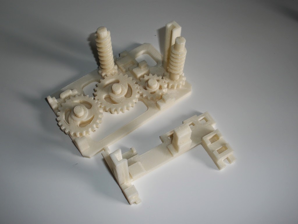
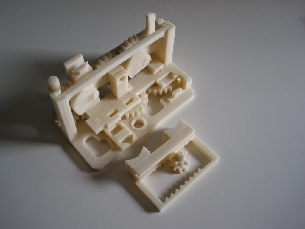
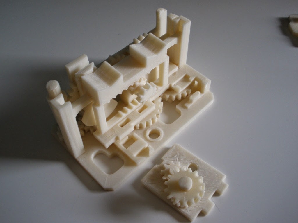
OK enough talking! Here are all the
elements of the “Walking Beam”! Next pictures show the assembly
of the whole machine. Isn't it even more awesome?


I am particularly proud of the
spirals. If you take a closer look, they have different slopes and
one is a single helix while the other is a double helix. For the
double helix system I also had to make the gear with inclined teeth
so it could fit within the gap. Here are some close-up pictures.


Finally I present to you the movie
with the Walking Beam in action!
Thanks for sticking this long. I do
hope you (or at least your inner-geek) enjoyed the content. I had
great fun making this project and am looking forward to doing some
more. Your “views”, “likes” and “shares” are an awesome
recognition to all this effort and for sure will boost my engines to
spend more time on 3d printing. Thank you!
No comments:
Post a Comment